General ISO Geometrical Tolerances Per. ISO 2768 | The following are general geometrical tolerances per. ISO 2768 for the following: - Linear Dimensions
- External Radius and Chamfer Heights
- Straightness and Flatness
- Perpendicularity
- Symmetry
- Runout
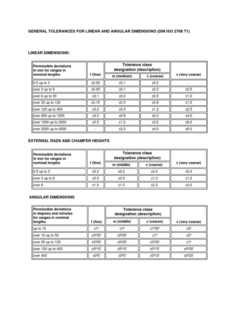
Related Mechanical Tolerance Design Data Variations on dimensions without tolerance values are according to ' ISO 2768'. All tolerance limits are given in mm. ISO 2768 and derivative geometrical tolerance standards are intendedto simplify drawing specifications for mechanical tolerances. ISO 2768 is mainly for parts that are manufactured by way of machining or removal of materials. Linear Dimensions: Permissible deviations in mm for ranges in nominal lengths | f (fine) | Tolerance class designation (description) | v (very coarse) | m (medium) | c (coarse) | 0.5 up to 3 | ±0.05 | ±0.1 | ±0.2 | - |
---|
over 3 up to 6 | ±0.05 | ±0.1 | ±0.3 | ±0.5 | over 6 up to 30 | ±0.1 | ±0.2 | ±0.5 | ±1.0 | over 30 up to 120 | ±0.15 | ±0.3 | ±0.8 | ±1.5 | over 120 up to 400 | ±0.2 | ±0.5 | ±1.2 | ±2.5 | over 400 up to 1000 | ±0.3 | ±0.8 | ±2.0 | ±4.0 | over 1000 up to 2000 | ±0.5 | ±1.2 | ±3.0 | ±6.0 | over 2000 up to 4000 | - | ±2.0 | ±4.0 | ±8.0 |
---|
External Radius and Chamfer Heights Permissible deviations in mm for ranges in nominal lengths | f (fine) | Tolerance class designation (description) | v (very coarse) | m (middle) | c (coarse) | 0.5 up to 3 | ±0.2 | ±0.2 | ±0.4 | ±0.4 | over 3 up to 6 | ±0.5 | ±0.5 | ±1.0 | ±1.0 | over 6 | ±1.0 | ±1.0 | ±2.0 | ±2.0 |
Angular Dimensions Permissible deviations in degrees and minutes for ranges in nominal lengths | f (fine) | Tolerance class designation (description) | v (very coarse) | m (middle) | c (coarse) | up to 10 | ±1º | ±1º | ±1º30' | ±3º | over 10 up to 50 | ±0º30' | ±0º30' | ±1º | ±2º | over 50 up to 120 | ±0º20' | ±0º20' | ±0º30' | ±1º | over 120 up to 400 | ±0º10' | ±0º10' | ±0º15' | ±0º30' | over 400 | ±0º5' | ±0º5' | ±0º10' | ±0º20' |
Straightness and Flatness Ranges in nominal lengths in mm | Tolerance class | H | K | L | up to 10 | 0.02 | 0.05 | 0.1 | over 10 up to 30 | 0.05 | 0.1 | 0.2 | over 30 up to 100 | 0.1 | 0.2 | 0.4 | over 100 up to 300 | 0.2 | 0.4 | 0.8 | over 300 up to 1000 | 0.3 | 0.6 | 1.2 | over 1000 up to 3000 | 0.4 | 0.8 | 1.6 |
Perpendicularity Ranges in nominal lengths in mm | Tolerance class | H | K | L | up to 100 | 0.2 | 0.4 | 0.6 | over 100 up to 300 | 0.3 | 0.6 | 1 | over 300 up to 1000 | 0.4 | 0.8 | 1.5 | over 1000 up to 3000 | 0.5 | 0.8 | 2 |
Symmetry (Position for ISO G&T Standard not-ASME or ANSI GD&T) Ranges in nominal lengths in mm | Tolerance class | H | K | L | up to 100 | 0.5 | 0.6 | 0.6 | over 100 up to 300 | 0.5 | 0.6 | 1 | over 300 up to 1000 | 0.5 | 0.8 | 1.5 | over 1000 up to 3000 | 0.5 | 1 | 2 |
Run-Out Tolerance class | H | K | L | 0.1 | 0.2 | 0.5 |
Related Resources: - Online GD&T Fundamentals
© Copyright 2000 - 2021, by Engineers Edge, LLC www.engineersedge.com All rights reserved Disclaimer | Feedback Advertising | Contact | Privacy Policy Date/Time:
|
| Home Engineering Book Store Engineering Forum Excel App. Downloads Online Books & Manuals Engineering News Engineering Videos Engineering Calculators Engineering Toolbox GD&T Training Geometric Dimensioning Tolerancing DFM DFA Training Training Online Engineering Advertising Center
|
|
|
- Iso 2768 Mk Tolerance Table Pdf
- Iso 2768 Mk Tolerance Table Saw
- Iso 2768-mh Tolerance Chart
- Iso 2768 Mk Tolerance Table
- Iso 2768-mh Tolerance Table
Iso 2768 Mk Tolerance Table Pdf
General tolerance ISO 2768 does not specify where to use these tolerances. As per design requirements and manufacturing capability tolerance class is defined. For example : For sheet metal parts ISO 2768–mk is used. And for machined components ISO 2768–fh can be used. In the above example “m” and “k” has defined the tolerance class.
Critical dimensions tolerance is calculated using tolerance stackup analysis. You can also use a tolerance stack up calculator for this purpose.
It is not possible to define tolerance against each dimension. Therefore variation in dimension without tolerance is defined using general tolerance. ISO 2768 has defined general tolerance for:
Table 6: General tolerances for symmetry (DIN ISO 2768 T2) The general tolerance for run-out and concentricity for class »K« is 0.2mm. In special cases for shape and position it is possible to choose tolerance class »H«. The general tolerance for run-out and concentricity for class »H« is 0.1mm. Mechanical Tolerance Chart Data. The following Engineering calculator will show the plus and minus tolerance for the specific ISO 286 Shaft tolerance data. Enter your desired preferred tolerance grade and the nomial size. Also see Table of Hole Tolerances per. Preferred tolerance grade ISO 286; International Tolerance Grades. General tolerance ISO 2768 does not specify where to use these tolerances. As per design requirements and manufacturing capability tolerance class is defined. For example: For sheet metal parts ISO 2768–mk is used. And for machined components ISO 2768–fh can be used. By the way, DIN 2768mk is a general tolerance table that provides the tolerances for anything that is not toleranced on the drawing, it does not refer to the diameter tolerances you are asking about. You can find info on the DIN 2768 at the link below. Split Cotter Pins (DIN 94 / ISO 1234) Circlips - Internal (DIN 472) Circlips - External (DIN 471) ISO Tolerances for Shafts (ISO 286-2) ISO Tolerances for Holes(ISO 286-2) Example limits and fits using hole basis; Machining Process Associated with IT Tolerance Grade; ISO Hole and Shaft Tolerance Band; Table of Typical Surface Hardness Values.
- Linear Dimensions
- Angular Dimension
- External Radius and Chamfer height
- Geometric Tolerance such as straightness, flatness, perpendicularity, symmetry and runout.
We suggest you read this article on go no-go gauges.
General Tolerance : ISO 2768
Linear DimensionsNominal Length Range in mmTolerance Classf
(fine)m
(Medium)c
(coarse)v
(very coarse)0.5 up to 3±0.05±0.1±0.2-3 up to 6±0.05±0.1±0.3±0.53 up to 30±0.1±0.2±0.5±130 up to 120±0.15±0.3±0.8±1.5120 up to 400±0.2±0.5±1.2±2.5400 up to 1000±0.3±0.8±2.0±4.01000 up to 2000±0.5±1.2±3.0±6.02000 up to 4000-±2.0±4.0±8.0External Radius and Chamfer HeightsNominal Length Range in mmTolerance Classf
(fine)m
(Medium)c
(coarse)v
(very coarse)0.5 up to 3±0.2±0.2±0.4±0.4over 3 up to 6±0.5±0.5±1.0±1.0over 6±1.0±1.0±2.0±2.0Angular DimensionsNominal Length Range in mmTolerance Classf
Iso 2768 Mk Tolerance Table Saw
(fine)m
(Medium)c
(coarse)v
(very coarse)up to 10±1°±1°±1°30'±3°over 10 up to 50±0°30'±0°30'±1°±2°over 50 up to 120±0°20'±0°20'±0°30'±1°over 120 up to 400±0°10'±0°10'±0°15'±0°30'over 400±0°50'±0°50'±0°10'±0°20'Straightness and FlatnessNominal Length Range in mmTolerance ClassHKLup to 100.020.050.1over 10 up to 300.050.10.2over 30 up to 1000.10.20.4over 100 up to 3000.20.40.8over 300 up to 10000.30.61.2over 1000 up to 30000.40.81.6PerpendicularityNominal Length Range in mmTolerance ClassHKLup to 1000.20.40.6over 100 up to 3000.30.61over 300 up to 10000.40.81.5over 1000 up to 30000.50.82SymmetryNominal Length Range in mm
Iso 2768-mh Tolerance Chart
Tolerance ClassHKLup to 1000.50.60.6over 100 up to 3000.50.61over 300 up to 10000.50.81.5over 1000 up to 30000.512RunoutHKL0.10.20.5
Iso 2768 Mk Tolerance Table
To sum up, Engineering tolerance is a very important and critical part of product design. And ISO-2768 standard defines the values of general tolerance. It is always recommended to run tolerance stackup analysis before design finalization.
Got Questions? We will be happy to help. If you think we missed Something? You can add to this article by sending a message in the comment box. We will do our best to add it in this post.
Iso 2768-mh Tolerance Table
Read this article for details on Limit Fit and Tolerance.